
Main Page |
Cluster Design and Fabrication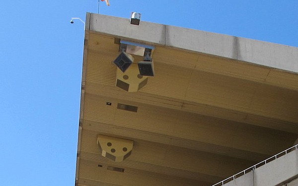
Designing a speaker system is one thing, then it has to get fabricated and installed. While 14 of the 16 roof mounted speaker clusters were perfectly square to the building structure, the north and south end speaker clusters covered listeners outside of the footprint of the roof, so the horn orientation and positioning had to be quite specific to hit those target coverage areas. The problem with something as symmetrical as a horn and driver is that in any CAD wireframe view, it constantly flips orientation as you look at it. Even looking at detailed ACAD drawings, the problem only gets worse as there is more detail to mislead the eye. Since a structural engineer had to draw and approve the speaker frame, communicating the actual arrangement was crucial to the project success. The position and orientation angles can be provided by the modeling software. 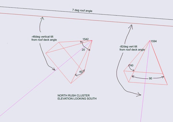 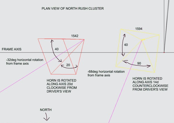 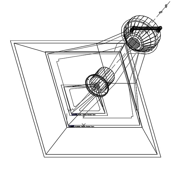 Is that pointing toward or away from me? Maybe it would be easier to envision if the aiming points can be identified and the horn orientation shown on the target areas in the model 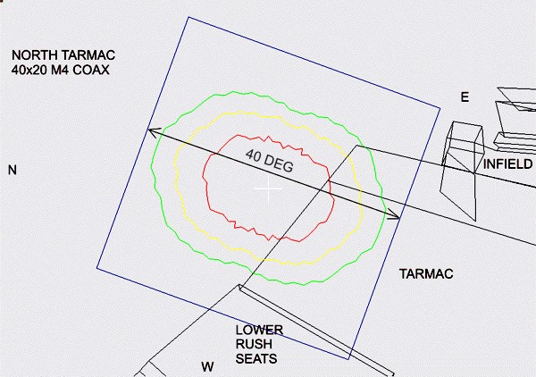 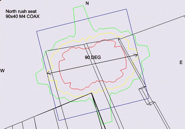 But even that relies on the viewer understanding that these are views of the target areas from the speaker's point of view. So those lines defining the target areas really only help when you have the rest of the model as a reference. So to provide the reference, the target aim points can be superimposed on a photo of the target areas. 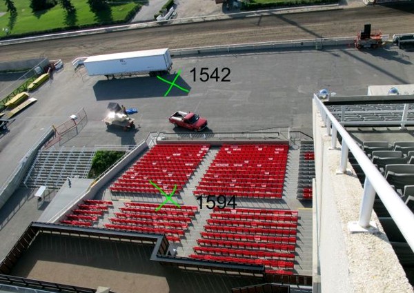 But even that makes it difficult to grasp how the horn is physically positioned, a full 3D ACAD cluster drawing only snaps into focus when you are able to keep the view moving so that the horns do not keep flipping around, pointing in and out of the screen. That doesn't help the guys with the tools in the fabrication shop. Sometimes the best skills are the ones you learned in kindergarten, so building a paper model of the two clusters was the easiest way to have everyone understand the orientation, and most importantly, be able to flip them over to fabricate the frames in an inverted position from the way they would attach to the roof. 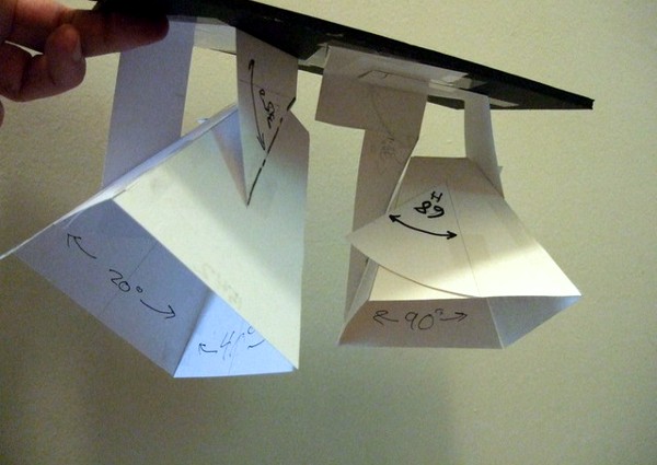 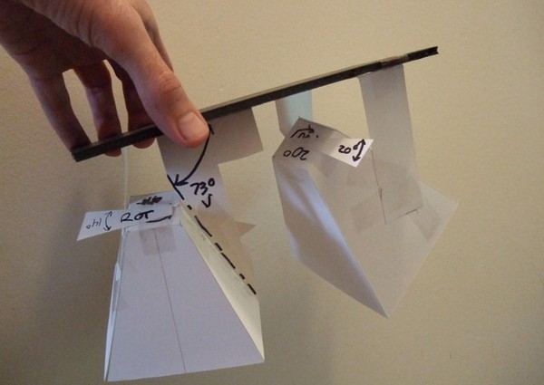 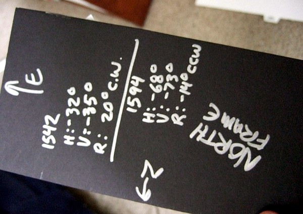 With the help of paper, glue stick and tape, a couple of paper models were built in a few hours, with the coverage angles of the horn shown, and the orientation angles shown, and shipped off by FedEx so that fabrication could continue on schedule. Once the horn frames were made, it was quite easy to arrange them in 3D space to match the angles on the models. 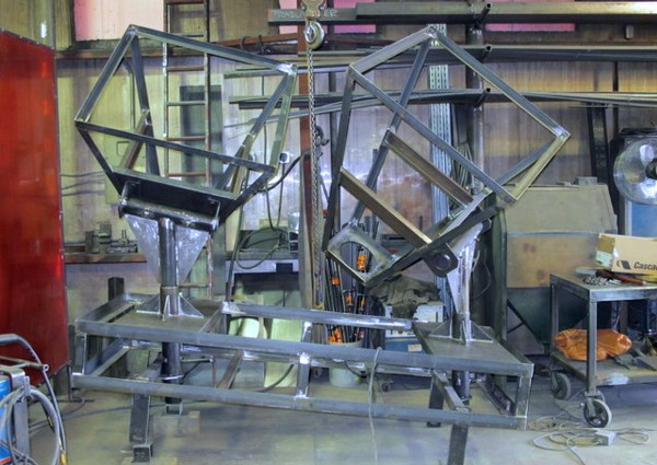 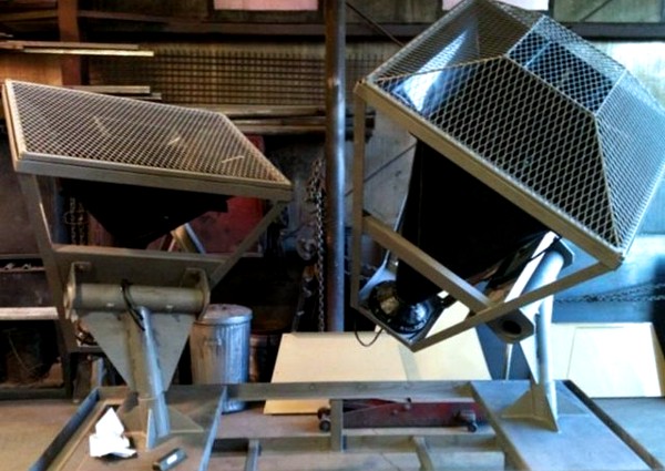 The net result was two cluster frames on the north and south end of the building that correctly oriented the horns straight out of the box. 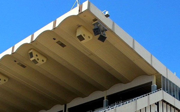 |